In the Steel Design add-on, I have set the boundary conditions in such a way that the I-beam flange is restrained against the horizontal displacement. I then calculated the critical load factors using the Structure Stability add-on, but with no effect on the critical load factor value. What is the reason for this?
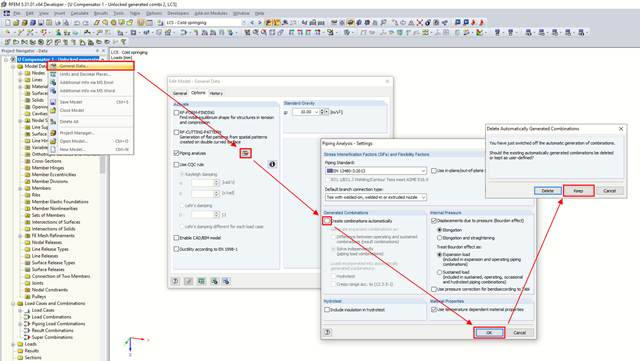
I design pipelines using the RF-PIPING Design add-on module. I have created a new prestress load case and loaded the piping with longitudinal displacement. Is it possible to add this new load case to combinations that are generated automatically?
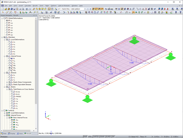
I have a trapezoidal roof structure supported by beams. However, the moments on the beams are smaller than they should be. What could be the reason for this?
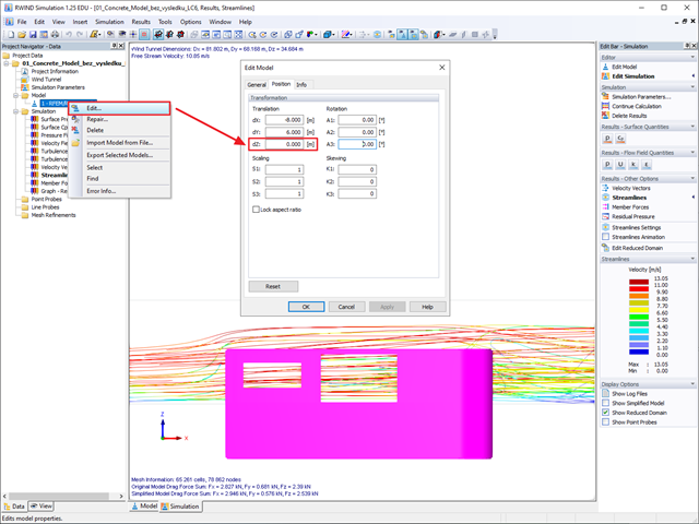
I saw somewhere that it is possible to set the ground level for a model in RWIND (for example, for a model with a basement). Unfortunately, I cannot find where to set this.
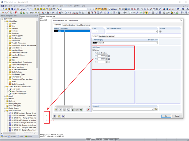
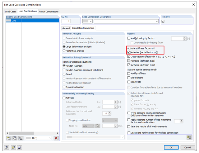
When calculating a membrane, the resulting deformation of load case LC1 and combination CO1 differs, although combination CO1 only contains LC1 with the factor of 1.00. What is the reason for this?
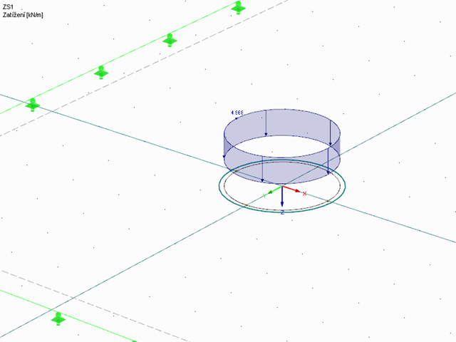
I have generated a load from an area load on a circular opening. If the radius is 1.0 m and the load is 10 kN/m², the resultant should be 31.416 kN. The recalculated load on the line should be 5.0 kN/m. However, the value of the converted load is 4.968 kN/m. Why?
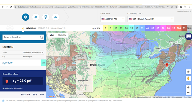
We would like use the online maps on your website to find snow, wind, and seismic loads. Can you please tell us more about activating and using this service?
![FAQ 005465 | In the Steel Design add-on, I have set the boundary conditions in such a way that the I-beam flange is restrained against the horizontal displacement. [*S16592627*]](/en/webimage/048136/3767383/5465_en.png?mw=640&hash=53de943721b7ae608ace1890d2b25738bed65d6b)
.png?mw=640&hash=9c3f4e9f5fdc2f866be8ffea74895e20cbcb7ea1)
.png?mw=640&hash=dac67ad19add530caa3ced6804658d4ec986733e)